Config Tool
Function
The Config Tool is needed to appropriately map the IO-Board inputs and outputs to a ROM in PinMame. The numbers of the inputs and outputs from PinMame are assigned to the inputs and outputs of the IO-Board firmware in the config file. In PinMame, original pinball ROM circuits are emulated. PPUC-Pinmame outputs the events of the circuit and accepts inputs for the emulated ROM. Without a config file, PPUC-Pinmame cannot communicate with the boards.
Config File
The Config Tool outputs a config file as a result. This file has the extension ".yml". The goal of your work, besides collecting pinball data, is primarily the generation of this file.
The YAML format used is very common for configuration files as it is a quasi-standard and easily readable by humans. In YAML, indentation determines which elements belong together and form a group. It is advisable not to edit this file manually, because a line break, a separator, or a space can easily be deleted, moved, or added, making the file unreadable. Caution! Do not modify the file manually.
Components of a Configuration
A configuration file for PPUC-PinMame consists of the following element groups:
- Game
- Boards
- DIP Switches
- Switches
- LED Stripes
- Lamps
- Flashers
- GI (Global Illumination)
- LEDs
- PWM-Outputs (Pulse Wide Modulation)
- Mechs
These are the important elements needed for the connection between Pinmame and IO-Boards. Additionally, all information about the pinball machine can be collected and archived in the configuration tool. This includes:
- Description
- Images (png, gif, jpg, jpeg, webp)
- ROM
- Manual
- Lamp Position Plan
- Switch Position Plan
- Solenoid Position Plan
First Steps
Important before we begin
Pinball machines usually have protective functions. Sometimes they are real switches, sometimes switching states in the machine's circuit. If you're building a playfield from scratch, or just want to try out part of the pinball machine, PinMame might not work as expected because you haven't created these states. Conditions are:
- Game On Solenoid
- Coin Door Closed Switch
PinMame uses the inputs of the original ROMs. Therefore, they are manufacturer-specific. E.g., Game On Solenoid: Williams System 3 - 11: 23 Williams WPC: 31 Data East: 23 Sega: 15 Gottlieb System 1: 17 Gottlieb System 80: 10 Gottlieb System 3: 32 Note: Also think about other switches that must be closed before a game starts. For example, whether a ball is in the ball trough. Possibly also whether enough balls are in the ball trough (switch at the last ball).
Installation and Launch of the Config Tool
Installation instructions
..
Interface
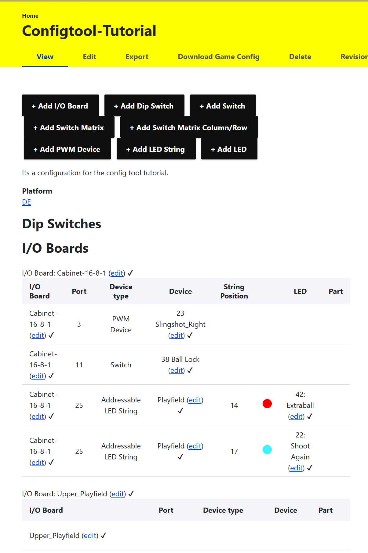
Home
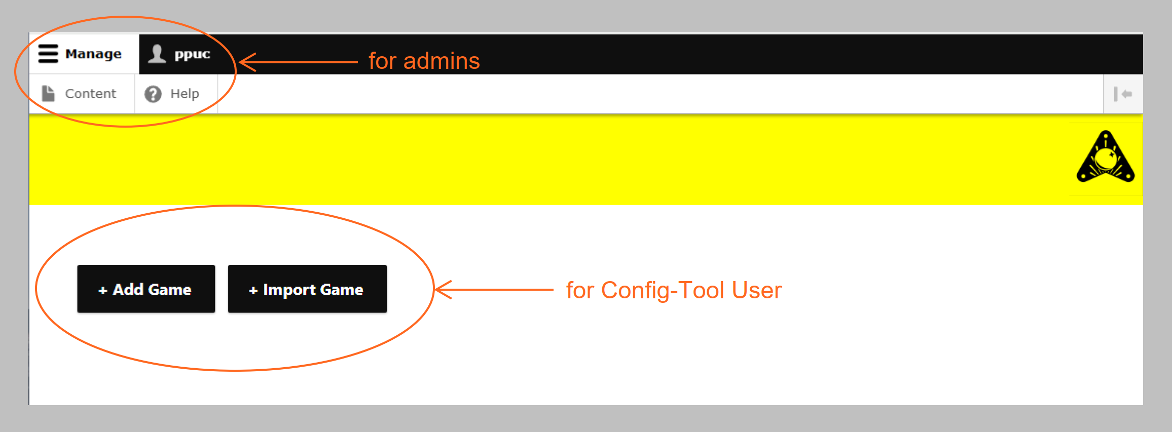
View

Summary of the Game elements.
Edit

Edit the inputs that were requested when creating the game. (Title, Description, Platform, Images, ROM, etc.)
Export

Save directly when clicking on Export. This saves the game completely. This file can be used to create backup copies of all inputs for the currently opened game. The save is placed in the browser's download folder.
Download Game Config

Save directly when clicking on Download Game Config. This saves the config file for use in PPUC-PinMame. The save is placed in the browser's download folder.
Delete

CAUTION: After confirmation, the currently opened element will be irrevocably deleted. The currently opened element (Game, LED-Stripe, LED, PWM-Device, Board, etc.) is deleted via this button. If you are in the game interface without having selected an element, the game will be deleted. Note when deleting a game: Only the game configuration is deleted. All associated boards, LED-Stripes, etc. remain. These will still be available for selection in the settings. If you want to delete the elements of a game, it's best to delete the subordinate elements first!
Revision

PPUC-Config Tool will make different versions of the game available in the future.
Clone

Elements such as Boards, LED-Strings, LEDs, etc. can be cloned using this button. This means that the element is cloned with the last saved inputs. You can recognize this by the extended title "Clone".
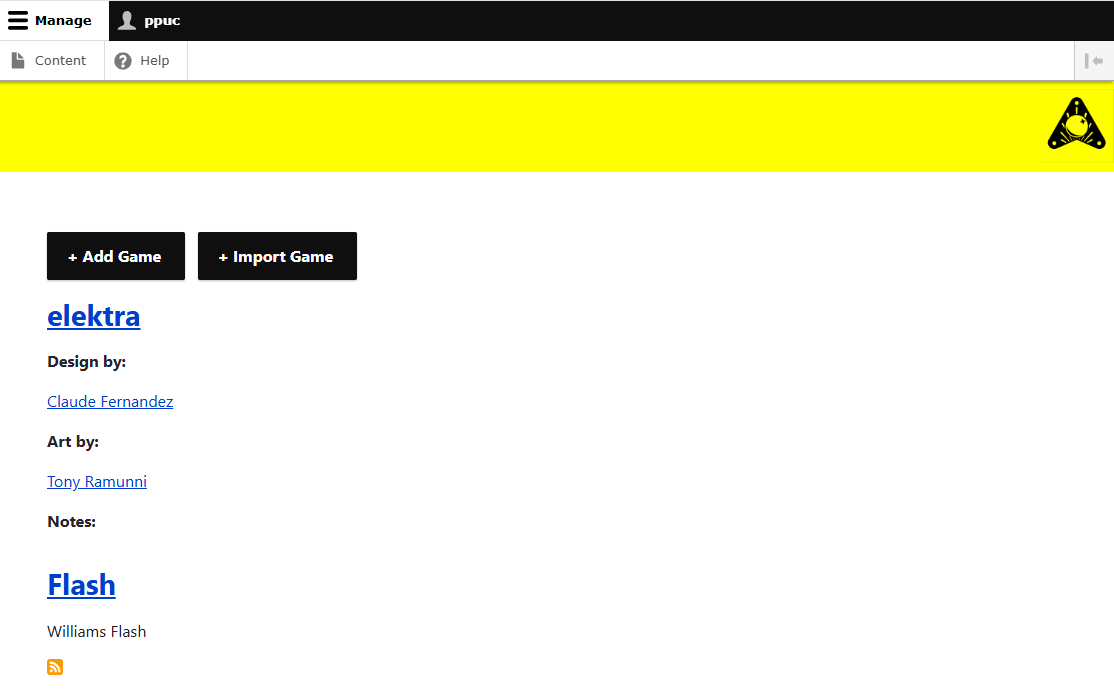
Creating a Game

A new game is created by pressing the "+ Add Game" button.
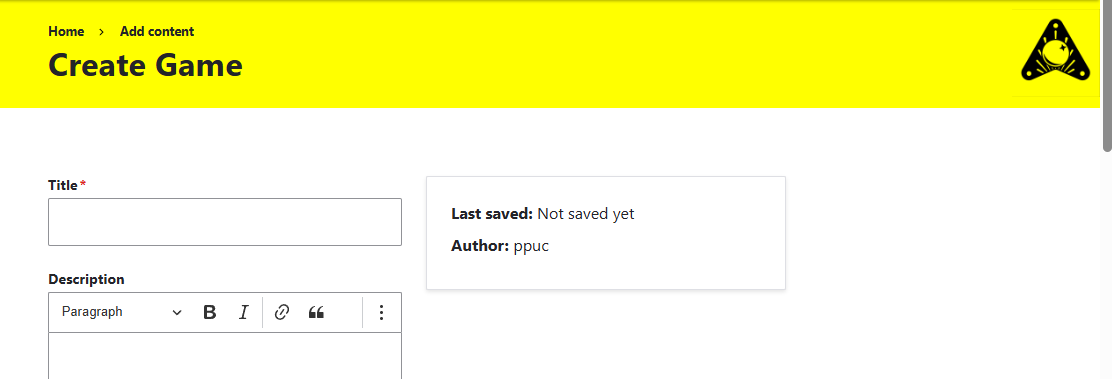
Now fill in the fields. Required fields are marked with asterisks (). *Don't forget** that your game may not start if you haven't defined Game On Solenoid and Coin Door Closed Switch.
Another important feature is the Platform.
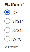
The manufacturers of pinball machines developed their systems over time and designed different platforms. The characteristics of the platforms are taken into account through the appropriate selection. There is not yet a separate selection for all platforms. DE = DataEast, SYS11 and SYS4
Save the data - You will receive confirmation that your game has been created.

You will automatically switch to the editor interface of the game.
Adding an IO-Board

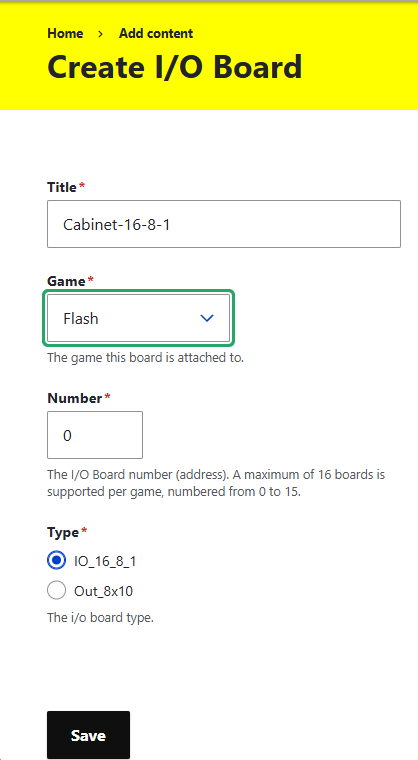
- Title: Choose a unique title that helps you identify the board.
- Game: Select the game you created earlier.
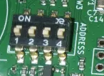
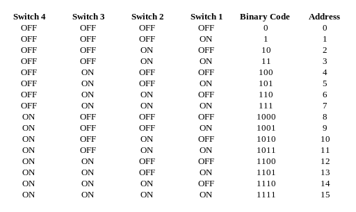
- Number: Enter the number of the I/O Board that you have set on the DIP switch on the board. The number can be set from 0 to 16. It is the address that tells the board it needs to respond to the data communication.
- Type: Also select the board type here.
- Note: The board, like other elements, can be assigned to multiple games. This might be important for you later when naming the board to recognize the boards.
Save - don't forget.
Inputs and Outputs
Microcontrollers whose I/O pins are routed outward are located on the boards. These I/O pins are used, among other things, for communication with each other and with the device running PinMame (RS485). The inputs and outputs are used to forward inputs from the pinball device to PinMame and to forward outputs from PinMame to the boards. The structure of the elements is hierarchical. For example, LED-Strings and PWM-Devices are assigned directly to the boards. Lamps, Flashers, and GI, however, are assigned to the LED-String.
Hierarchy:
- Game
- Board
- DipSwitch
- Switch
- Switch Matrix
- Matrix Column
- Matrix Row
- LED String
- Lamps
- Flashers
- GI
- PWM Device
- Board
After you have created a game and a board, now add the elements.
DIPSwitch
Switch
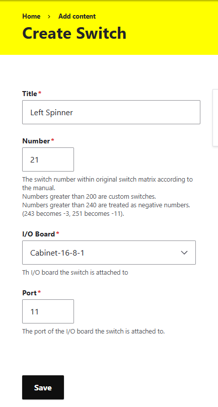
- Title: Choose a unique title that helps you identify the board.
- Number: This number is received by PinMame from the board and evaluated in the simulated ROM. This means that the number must be the same number that is used in the ROM. You can find this number in the manual of the pinball machine.
- Number greater than 200: no longer belongs to the PinMame ROM, but is evaluated as Custom Switches (user-defined switches). These can trigger events in VPX-Boards in the future.
- Numbers greater than 240: are evaluated by PinMame as negative numbers. 240 is automatically subtracted from this number and a negative sign is prefixed. Examples: 241= -(241-240) = -1, 243 = -3, 260 = -20
- I/O Board: The I/O board to which the switch is connected.
- Port: The number of the input on the I/O board.
Switch Matrix
Matrix Column
Matrix Row
LED String
This controls WS2811, WS2812, and other addressable LEDs, also RGBW like SK6812. It doesn't have to be a chain. It can also be strips, or individual LEDs that are connected to each other in another way. The principle of these LEDs, however, is to form a continuous chain, in which the data line only goes in one direction and only as one strand, never in a circle. For control, data is sent to the corresponding LED. This data packet passes by all connected LEDs. Only the LED with the corresponding number responds.
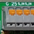
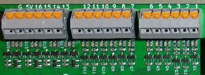
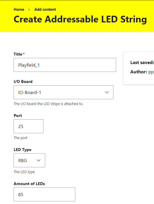 Title: Choose a unique title that helps you identify the light chain. I/O Board: The I/O board to which the LED chain is connected. Port: Port number of the board to which the LED chain is connected. For the I/O Boards 16-8-1, this is port 25. See the labeling on the board:
 LED Type: Here the color type is specified. Whether RGB, GBR, BRG, RGBW, and so on... The transferred color values are put into the right order with this. Amount of LEDs: Number of LEDs in the chain.
Segments
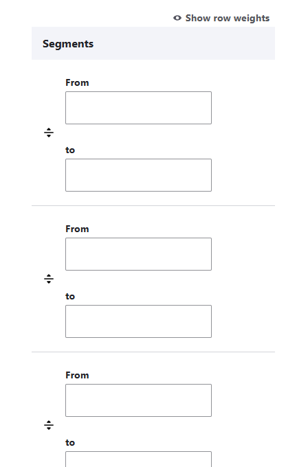
The light chain can be divided into segments. This serves to apply animated light effects to certain sections of the chain. These effects are predefined and stored in the firmware of the boards and can be triggered. From - to defines the position of the first and last LED of the respective section in the chain.
Light
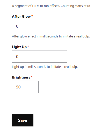
- After Glow (Milliseconds): The brightness of the LED is faded out and not switched off abruptly. This simulates the behavior of the incandescent lamps of the old devices.
- Light Up (Milliseconds): The brightness of the LED is faded in and not switched on abruptly. This simulates the behavior of the incandescent lamps of the old devices.
- Brightness (0-255): Defines the brightness of the entire LED chain.
LED
Add LEDs to your LED chain. You can create each LED individually, or use the Clone function to adopt parameters.
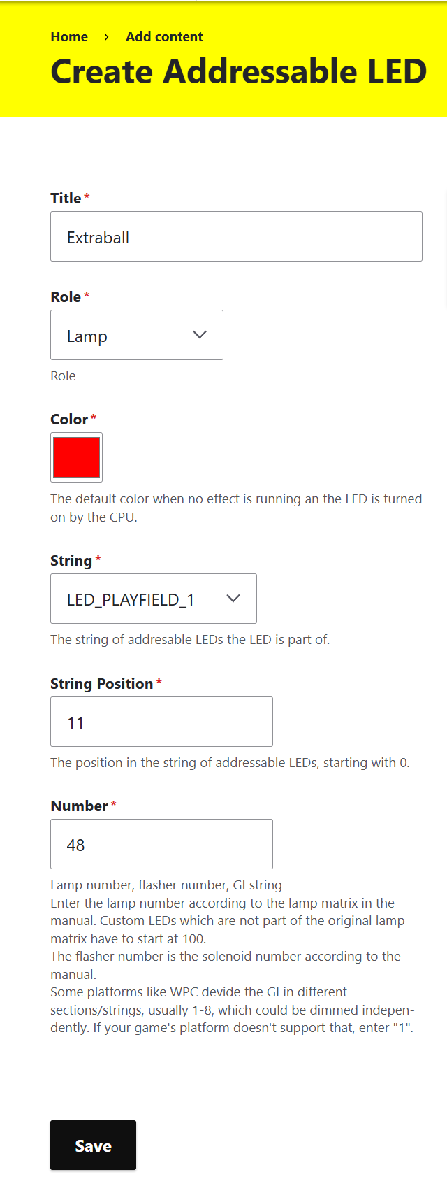
- Title: Choose a unique title that helps you identify the lamp.
- Role: Here you select the type of imitated lamp of the pinball machine. There are Lamp, Flasher (5V), GI. See the description of the lamp types a bit further down.
- Color (255, 255, 255): Here you can determine the color value of the lamp. Note that this also makes the lamp darker if values are below 255.
- String: Here you select the previously created light chain to which this LED belongs.
- String Position: The position number of the LED in the order of the data line of the chain.
- Number: This number is received by the board from PinMame from the simulated ROM. This means that the number must be the same number that is also used in the ROM to control this lamp. You can find this number in the manual of the pinball machine.
Lamps
Lamps are LEDs that are controlled and display certain game states and events.
Flashers
Flashers are LEDs that draw attention to game events in a particularly effective and bright way.
GI
GI means Global Illumination. This is the basic lighting of the pinball machine and not every LED is specifically controlled. Usually, the GI light is switched on as soon as the game starts.
PWM Device
PWM Device refers to the electromagnets or other pinball hardware (usually installed on the playfield) that are controlled at the I/O-Board outputs with higher voltage. This also includes particularly bright lamps and flashers. For example, up to 60 volts for the I/O-Board 16-1-1.
Pulse Width Modulation (PWM) is a technique where the output voltage is regulated by rapidly switching the current flow on and off and varying the on-time (pulse width). A longer on-pulse results in a higher average output voltage, while a shorter pulse creates a lower voltage. This method allows efficient and precise control of power output. PWM is also used to keep the output voltage stable, even if the load changes. In addition, it allows the control of LED brightness, motor speed, and power output to many other electronic devices.
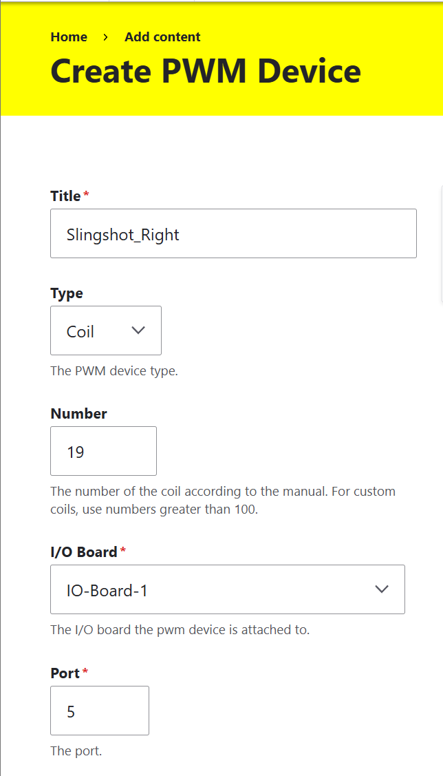
- Title: Choose a unique title that helps you identify the PWM-Device.
- Type: Since there are different types of controllable hardware with higher voltage, select the corresponding type here.
- Number: This number is received by the board from PinMame from the simulated ROM. This means that the number must be the same number that is also used in the ROM to control this hardware. You can find this number in the manual of the pinball machine.
- I/O Board: The I/O board to which the LED chain is connected.
- Port: The number of the output to which the hardware to be addressed is connected. Example I/O-Board 16-1-1:
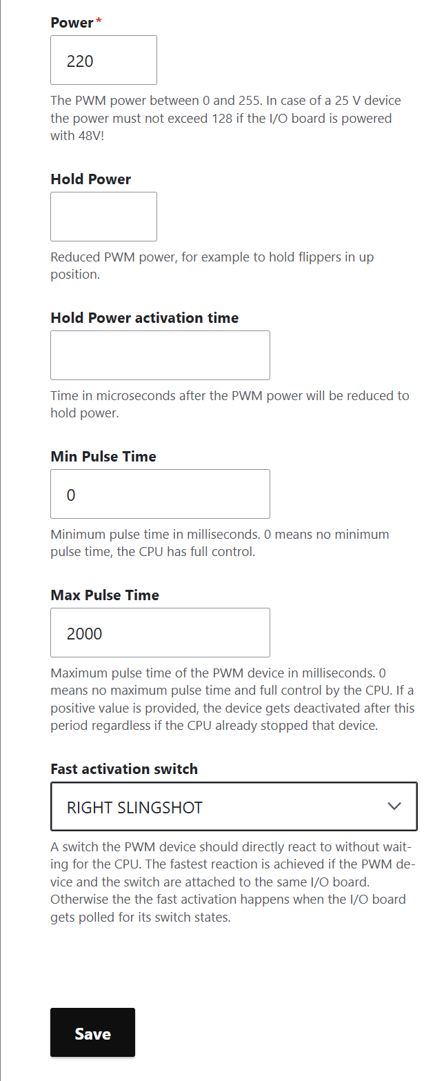
- Power (0-255): 0 = 0 Volt. 255 = full power supply performance (pay attention to the max allowed voltage). Values between 0 and 255 reduce the power supply voltage.
- Note: The power supply voltage does not reduce linearly! You must measure the voltage corresponding to the value before using it.
- Hold Power (0-255): With Hold Power, the power supply voltage can be reduced after the power under Power has been reached. This can be used, for example, to pull flipper fingers with full power and then hold them with reduced voltage to protect or spare the coil from burning out. The voltage is determined in the same way as the Power voltage.
- Hold Power activation time: The time for which the full voltage is applied and from then on the reduced holding voltage is switched on.
- Min Pulse Time (ms): ? ? ?
- Max Pulse Time (ms): After this set time, the voltage at the output is set to 0. This function serves to protect the hardware at this output from overheating. E.g. if there is a software error. Or if a linked input does not send the signal to turn off the output.
- Fast activation switch: This function serves to directly connect a switch with an output. A previously defined switch is selected in this dropdown field. The switch triggers the output directly via the board. For this, the detour via PinMame is not taken. E.g. for the fastest possible reaction time. Additional effects can also be built in, or the software can be changed. For example, a bumper can be implemented with it, without the software having to recognize and trigger it. But the fastest reaction of the solenoids of the flipper fingers to the flipper buttons can also be implemented with this. Note: The switch and the output must both be on the same board. And not all inputs are for ...???
Typical Example Settings:
Warning: simply copying these examples can damage the hardware!
Flipper Fingers: Bumper: Drop Target Up: Outhole:
View
Here you'll always have an overview of all elements added to the game. You can also edit them directly by clicking Edit.
Config File Export
This button in the side header of a selected game saves the complete information that has been added to the game. The file name is generated from the Game Title. The file is written in plain text in YAML format. You use this file with PPUC-Pinmame. With this, the PPUC part in PinMame learns the structure of the board configuration. You can create different configurations and use them in PPUC-Pinmame.
Save Configuration Completely
This button in the side header of a selected game saves the complete information that has been added to the game. The file name is strangely long, but this makes it unique and machine-readable. You should regularly create a backup using this button. After triggering the button, the file is immediately saved to the browser's download folder. This file can be loaded later (Game Import) or passed on. The file is not saved in plain text and includes ROM and image files.
Troubleshooting
If you encounter issues with your configuration, here are some common problems and solutions:
- If PinMame does not respond to your inputs, double-check that your Game On Solenoid and Coin Door Closed Switch are properly configured
- Verify that board numbers and port assignments match your physical hardware setup
- For LED chains that don't light up correctly, confirm the LED Type setting matches your actual hardware (RGB vs GRB, etc.)
- When using PWM devices, start with low power values and gradually increase to avoid damaging components
- Remember to save your configuration regularly using the Export button to avoid losing your work
Something missing or wrong? You can fix it!
This website is edited by people like you! Is something wrong or missing? Is something out of date, or can you explain it better?
Please help us! You can fix it yourself and be an official "open source" contributor!
It's easy! See our Beginner's guide to editing the docs.
Page navigation via the keyboard: < >
You can navigate this site via the keyboard. There are two modes:
General navigation, when search is not focused:
- F , S , / : open search dialog
- P , , : go to previous page
- N , . : go to next page
While using the search function:
- Down , Up : select next / previous result
- Esc , Tab : close search
- Enter : go to highlighted page in the results